
Replace a Lenovo ThinkPad X220's BIOS with an open-source UEFI-capable firmware
Introduction
There are many guides on the internet that deal with replacing the firmware of older ThinkPad notebooks with coreboot. However, most of these guides use SeaBIOS as a payload for coreboot, which limits the notebook to booting operating systems exclusively using a legacy BIOS. This is quite a downgrade from the X220’s original firmware, since the X220 was part of the first generation of ThinkPad notebooks that could boot UEFI natively.
This guide instead uses TianoCore EDK II as a payload. Specifically, it concerns this fork by MrChromebox since it is the default that coreboot uses. EDK II allows UEFI booting. But what about legacy BIOS support?

The X220 was originally released with Microsoft Windows 7, which was the first Windows version to support installation and booting on UEFI systems. The original firmware also includes a Compatibility Support Module (CSM), which allows an UEFI system legacy BIOS boot. Since UEFI itself is supported and operating systems from Windows 7 onward support UEFI, there never was a really good reason to use the CSM. If the goal is to run an older operating system, virtualization and emulation provide much better options for a notebook like the X220. It is 2024. Time to say goodbye and go back to the future!
What will this guide based on coreboot and TianoCore EDK II offer you and your X220?
- The ability to boot your X220 using UEFI from SATA and USB storage. This is the same capability that the original firmware has, so not that exciting.
- The ability to boot your X220 using PXE in UEFI. I haven’t found any other guide on the internet which explains how to make this combination (coreboot+EDK II + iPXE) work. The X220’s original firmware can only boot PXE using its CSM, not in UEFI mode. Also, the (open source, of course!) iPXE-based EFI driver supports IPv6, which is something that the original firmware is unable to use.
- TPM and Secure Boot support. The former is supported by the original firmware, but the X220 came out in a time that Secure Boot did not exist. Now we add support for it anyway, because why not?
- A thoroughly stripped down and disabled Intel Management Engine (optional but highly recommended).
- As a positive side effect, you are not limited in which Mini-PCI Express cards you are allowed to use. It is possible to upgrade your Wi-Fi card to a newer Wi-Fi standard without the firmware preventing the system from booting.
- That warm, fuzzy feeling you get when you run open source software!
Of course, you’ll do everything at your own risk.
What you will need
- A Lenovo ThinkPad X220 notebook.
- Another computer with which the SPI flash chip of the notebook can be read and written. It is assumed this computer runs Arch Linux or Arch Linux ARM. This computer can also be used to build the open-source firmware, but you can also do that on a different computer.
- An SPI interface supported by flashrom. It is required to directly interact with the X220’s SPI flash chip to work around security features of the original firmware. Two interfaces are noted in this guide:
- A CH341A programmer. WARNING: Many of these programmers seem to provide 5V instead of 3.3V on their data pins. I learned this after I flashed my X220. So far it did not hinder the flashing process or damage my X220. Your mileage might very. If in doubt, modify an older CH341A or buy a newer revision with a voltage selection switch, or use…
- A Raspberry Pi. Each Pi with a 40-pin GPIO connector supports SPI. If you use a Pi, also have some (at least six) female-to-female jumper wires. An advantage of using a Raspberry Pi is that it is a lot faster. It also provides 3.3V on the data pins, which is within specifications of the SPI flash chip on the X220.
- A SOIC8/SOP8 test clip, to use as a physical interface for the notebook’s SPI flash chip. If you do not have one of these, buy a CH341A programmer kit that includes one. It should have an adapter board included that will allow you to interface it with the CH341A programmer or to any other device using female jumper cables. Such a kit can be picked up for a couple of (euro)bucks on eBay or AliExpress.
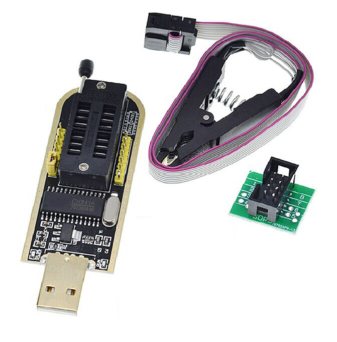
In the picture above you see a CH341A programmer on the left, a test clip at the top, and the adapter board to connect both devices with each other to the right. A CH341A kit might also include other components, but they are not necessary to flash an X220. You can opt to ignore the (possibly faulty) programmer and use the test clip and the adapter board with a Raspberry Pi instead. The bottom of the adapter board accepts female jumper cables, which can directly connect the pins to the Pi. The required pinout is given further along in this guide.
Read original firmware from chip
The first step is getting a copy of the original firmware from your X220. This is required due to that some binary blobs must be extracted from it. The original firmware can also be used to restore your X220 to original condition should you ever want to. A copy of the specific firmware of your notebook is needed since it contains some unique identifiers. Also, by extracting your own copy it is not necessary to distribute copyrighted proprietary files.
Before you begin
This guide focuses on a Lenovo ThinkPad X220, but most parts also apply to similar notebooks. As far as I am aware, all chips used in ThinkPad notebooks operate at 3.3V. However, never just assume this. Always verify acceptable voltages, no matter what device you are working on. If you do not, you risk releasing the once-upon-a-lifetime blue magical smoke!
As noted in the previous section, I have also tested this with a faulty CH341A. Many of these programmer boards output 5V on the data lines instead of 3.3V. In my case it was fine, but remember that not all chips might be so tolerant. There are also chips in the wild (probably not on ThinkPads) which operate at 1.8V, which require either an adapter or a voltage selector on the programmer.
Look up the specifications of the chip you want to flash. My X220 has a Winbond 25Q64FV, which accepts 3.3V according to its datasheet. If I would repeat this, I will either use a CH341A revision 1.7 (which has a voltage selector) or a Raspberry Pi.
Installing prerequisites
Install flashrom on the device that you want to use to read and write the SPI flash chip with:
sudo pacman -Syu --noconfirm --needed flashrom
This is all the software needed for reading and writing the flash chip.
Preparing a CH341A programmer
The CH341A does not need any software preparation. The only thing you need to do is wire it all up.
Start by installing the SOP test clip adapter into the ZIF socket of the CH341A like this:
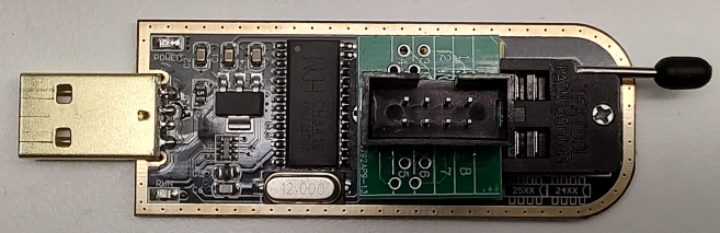
Note the orientation! The adapter has the same pin numbers as an SPI flash chip. Pins 4 and 5 are at the edge of the socket, furthest from the release lever.
The included test clip can only be connected in a single orientation to the adapter (red wire = pin 1). Do so.
Preparing a Raspberry Pi
Using root privileges, open /boot/config.txt in your favorite text editor. Add the following line at the top:
device_tree_param=spi=on
Reboot the Pi.
Now wire the test clip to the 40-pin GPIO connector based on the following schematic. Pi pinout courtesy of pinout.xyz.
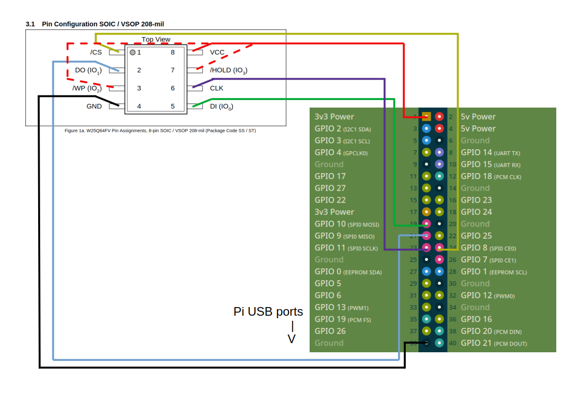
This is the “official” layout I find in different places on the internet which describe how to wire a Pi to an SPI flash chip. In my limited experience, /HOLD and /WP (the dotted red lines in the schematic) are optional and can be ignored. Just wire 3v3 power to VCC only.
Make a physical connection
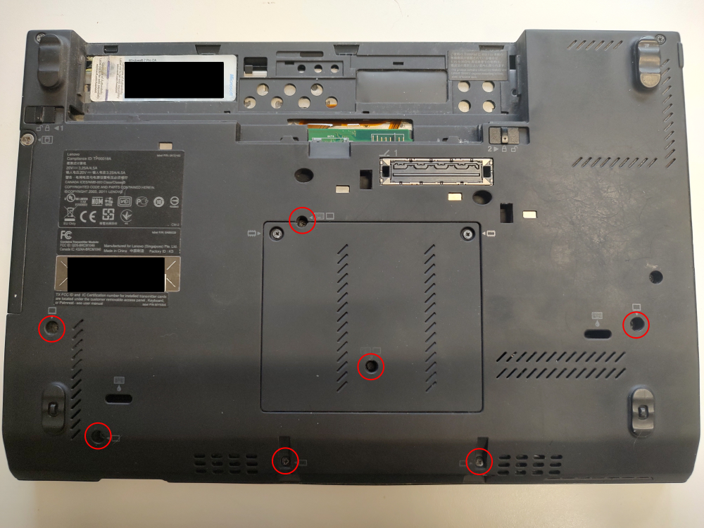
Make sure that the X220 is not connected to anything. Remove its battery. Turn it over and remove the seven screws securing the keyboard and palm rest.
Flip the notebook over again and open the display. Push the keyboard towards the display for a bit. Use something nonconducting and soft but sturdy (plastic prying tool, bank card…) to gently lift the bottom of the keyboard up and free from the palm rest. Be careful. The keyboard is connected to the X220’s mainboard with a single ribbon cable. It is not necessary to disconnect the keyboard.
With the keyboard free from the palm rest, lift the palm rest. Start at the upper edges (below the freed keyboard). Just lift it up until it is free from the chassis while still being under the keyboard. The palm rest is connected to the X220’s mainboard with a single ribbon cable to support the touchpad and fingerprint reader (if installed). It is not necessary to disconnect it. Just gently place the palm rest underneath the keyboard to get space to work. You should be able to see the Wi-Fi adapter, WWAN adapter (if installed), CMOS battery, Bluetooth adapter, and the top of the ExpressCard slot.
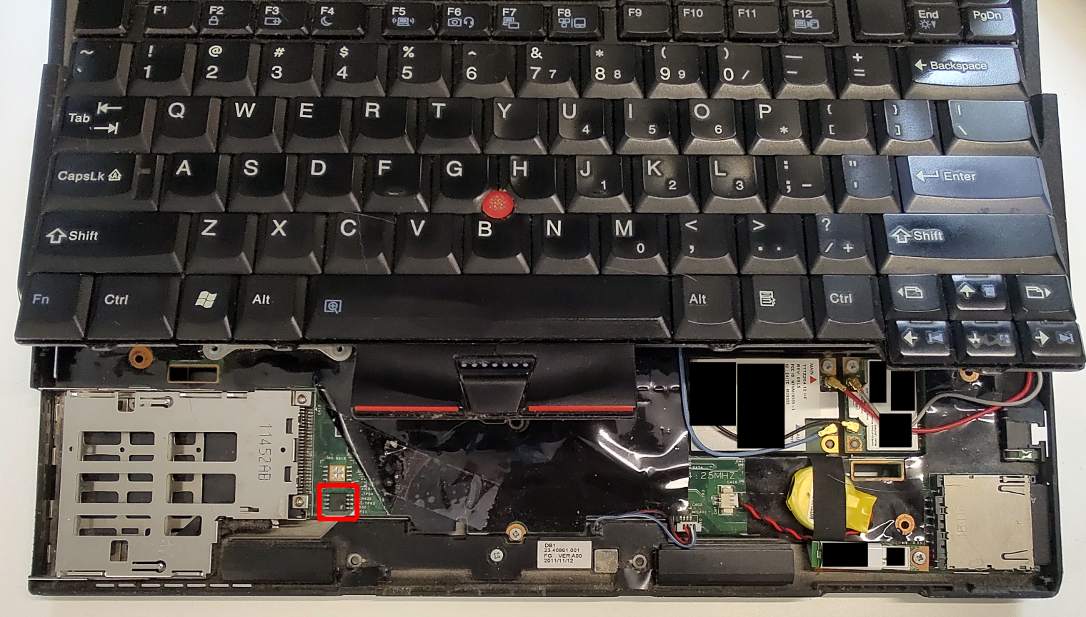
The mainboard of the X220 is covered with black plastic sticky film. It is not necessary to remove it all. Just lift up a single corner to expose the SPI flash chip. In the picture you see that I did this using a piece of sticky tape to keep the film out of the way while I am working on the notebook. The flash chip is marked red.
Place the test clip on the SPI flash chip in the proper orientation. Pin 1 (red on the flat cable of the test clip included with a CH341A) is on the side facing the yellow CMOS battery and the outer edge of the notebook (away from the display and ExpressCard slot).
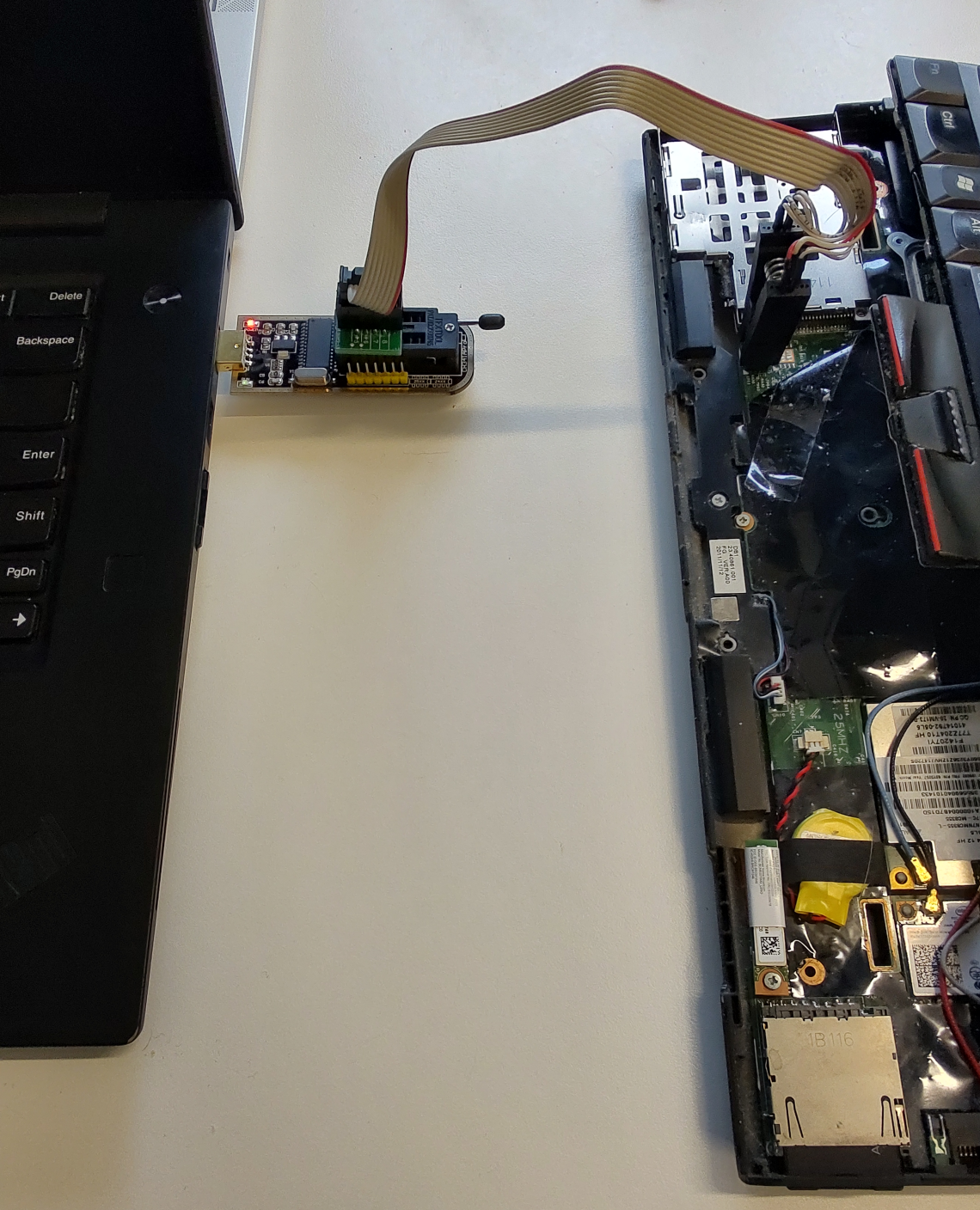
Test the connection to the chip.
Using a CH341A, run:
sudo flashrom --programmer ch341a_spi
With a Raspberry Pi using its 40-pin GPIO connector, run:
sudo flashrom --programmer linux_spi:dev=/dev/spidev0.0,spispeed=15000
A successful result will identify the chip:
Found Winbond flash chip "W25Q64.V" (8192 kB, SPI) on ch341a_spi.
A failed result will look like this:
No EEPROM/flash device found.
Note: flashrom can never write if the flash chip isn't found automatically.
If the connection fails, reposition the test clip and try again. Make sure to open and close the clip while doing so. Continue once a successful connection is made.
Read the original firmware from the chip
There is no data error correction between the chip and the device connected to it. Therefore, it is required to read the firmware multiple times and compare the results. If no differences are found, it is very likely that the retrieved data is correct.
Using a CH341A, run:
cd ~/src
sudo flashrom --programmer ch341a_spi --read x220.bin.1
With a Raspberry Pi using its 40-pin GPIO connector, run:
sudo flashrom --programmer linux_spi:dev=/dev/spidev0.0,spispeed=15000 --read ~/src/x220.bin.1
A successful read will output something like this (based on a CH341A):
flashrom v1.2 on Linux 6.8.1-arch1-1 (x86_64)
flashrom is free software, get the source code at https://flashrom.org

Using clock_gettime for delay loops (clk_id: 1, resolution: 1ns).
Found Winbond flash chip "W25Q64.V" (8192 kB, SPI) on ch341a_spi.
Reading flash... done.
The CH341A in particular is quite slow, and it can take around five minutes before reading is finished and “done.” shows up.
If read successfully, repeat the comand with an output to file x220.bin.2. If that also reads succesfully, run:
diff ~/src/x220.bin.1 ~/src/x220.bin.2
If there are differences, repeat the reads and comparison.
If there is no output from diff then both files are the same. Run:
sudo chown $USER:$USER ~/src/x220.bin.*
rm ~/src/x220.bin.2
mv ~/src/x220.bin.1 ~/src/x220.bin
Store x220.bin somewhere safe. This file is required if you ever want to revert to the original firmware. Note that it is specific to the notebook where it came from. It contains the MAC address of the Ethernet adapter, and possibly other unique identifiers.
Create coreboot image
Installing prerequisites
The operating system needs to provide some development packages to kickstart the creation of an open-source BIOS.
sudo pacman -Syu --noconfirm --needed base-devel gcc-ada nasm imagemagick
Get coreboot
mkdir -p ~/src
git clone https://review.coreboot.org/coreboot.git ~/src/coreboot
Prepare building environment
Build (cross-)compilation environment.
cd ~/src/coreboot
make crossgcc-x64 CPUS=$(nproc --all)
This will take around 18 minutes on a recent six core CPU.
Prepare binary blobs
Some binary blobs are needed to create a full firmware package. These must be extracted from the original firmware that was previously read from the chip (x220.bin).
cd ~/src/coreboot/util/ifdtool/
make

cd ~/src
~/src/coreboot/util/ifdtool/ifdtool --extract x220.bin

mkdir -p ~/src/coreboot/3rdparty/blobs/mainboard/lenovo/x220
cp flashregion_0_flashdescriptor.bin ~/src/coreboot/3rdparty/blobs/mainboard/lenovo/x220/descriptor.bin
cp flashregion_2_intel_me.bin ~/src/coreboot/3rdparty/blobs/mainboard/lenovo/x220/me.bin
cp flashregion_3_gbe.bin ~/src/coreboot/3rdparty/blobs/mainboard/lenovo/x220/gbe.bin
Fully optional, but it is nice to have a splash screen when the system boots up. Get one using:
cd ~/src/coreboot
curl -JLO https://kiljan.org/downloads/thinkpad/bootsplash.png
Credits for the image go to @nenadstoisavljevic. The original image was taken from nenadstoisavljevic/x220-coreboot-guide and is supposed to be used full screen with a SeaBIOS payload. All I did was crop the logo so it shows up nicely in TianoCore EDK II.
Configure coreboot
mkdir -p ~/src
cd ~/src
git clone https://review.coreboot.org/coreboot.git
cd ~/src/coreboot
make nconfig
Configure as follows:
Mainboard -> Mainboard vendor -> Lenovo
Mainboard -> Mainboard model -> ThinkPad X220
Mainboard -> Size of CBFS filesystem in ROM ->
0x300000(=3 MB)Chipset -> Add Intel descriptor.bin file -> enable
Chipset -> Add Intel ME/TXE firmware -> enable
Chipset -> Add gigabit ethernet configuration -> enable
Chipset -> Run coreboot in long (64-bit) mode
Generic Drivers -> PS/2 keyboard init -> enable
Payload -> Payload to add -> edk2 payload
Payload -> edk2 Bootsplash path and filename ->
bootsplash.png(only if a custom boot splash screen is prepared, leave it default otherwise)Payload -> Use Escape key for Boot Manager
Save the configuration with F9 and save (the default option).
It might be tempting to select the option Chipset -> Strip down the Intel ME/TXE firmware. Do not do this. During the build process, coreboot applies a rather tame method to disable Intel Management Engine, which keeps the complete blob in the image. After building the firmware for the first time, some improvements will be suggested for a second build. One of these improvements also disables ME while reducing its size from ~5 MB to 84 KB.
Build coreboot for the first time
The coreboot build process is pretty intelligent and intuitive. The only command needed is:
make
The result should look something like:
FMAP REGION: COREBOOT
Name                           Offset     Type           Size   Comp
cbfs_master_header             0x0        cbfs header        32 none
fallback/romstage              0x80       stage          104048 none
cpu_microcode_blob.bin         0x19780    microcode       26624 none
fallback/ramstage              0x1ffc0    stage          124328 LZMA (378568 decompressed)
config                         0x3e5c0    raw              3430 LZMA (11023 decompressed)
revision                       0x3f380    raw               721 none
build_info                     0x3f680    raw               104 none
fallback/dsdt.aml              0x3f740    raw             14732 none
vbt.bin                        0x43100    raw              1400 LZMA (3985 decompressed)
cmos_layout.bin                0x436c0    cmos_layout      1976 none
fallback/postcar               0x43ec0    stage           28016 none
fallback/payload               0x4ac80    simple elf    1399688 none
(empty)                        0x1a0840   null            17764 none
bootblock                      0x1a4dc0   bootblock       45056 none

Built lenovo/x220 (ThinkPad X220)
If it does, you just built your first (mostly) open-source BIOS image. Neat! However, there is some space for improvement. The created image still contains Intel Management Engine, while it lacks network boot support. Time to rectify this!
Improve coreboot
The created image could now be flashed to the notebook, but some improvements can be made first.
Strip Intel Management Engine
Much has been written about Intel Management Engine. This guide is not going into the nitty gritty details. It is sufficient to say that it is a feature that does not benefit end users in any way, so nothing will be missed. It will be reconfigured so that it disables itself during boot. A bonus is that this will free up space in the image since unused parts of ME will be removed.
git clone https://github.com/corna/me_cleaner.git ~/src/me_cleaner
~/src/me_cleaner/me_cleaner.py -t -r ~/src/coreboot/3rdparty/blobs/mainboard/lenovo/x220/me.bin
Add network boot support
The coreboot build environment only can build network boot support for legacy BIOS configurations, which is something that will not be used. A bit of work outside of coreboot will be necessary to add UEFI network boot support. An EFI driver will be made for the specific network card in the X220 and added to TianoCore EDK II.
First, download the source of the wonderful iPXE:
git clone https://github.com/ipxe/ipxe.git ~/src/ipxe
Edit ~/src/ipxe/src/config/general.h in your favorite text editor. Uncomment the line containing #define NET_PROTO_IPV6 to enable IPv6 support. Save and exit.
Now build the EFI driver:
cd ~/src/ipxe/src
make bin-x86_64-efi/80861502.efidrv
The changes to EDK II can be injected into the build environment that coreboot created for it when the firmware was first built.
cp ~/src/ipxe/src/bin-x86_64-efi/80861502.efidrv ~/src/coreboot/payloads/external/edk2/workspace/mrchromebox/UefiPayloadPkg/NetworkDrivers/net.efidrv
Open the file ~/src/coreboot/payloads/external/edk2/workspace/mrchromebox/UefiPayloadPkg/UefiPayloadPkg.fdf in your favorite text editor. Add the following directly below the comment block containing Network modules (only available on X64):
FILE DRIVER = CF1E0AF2-ADC4-4306-AFE0-2B33FF0310E1 {
  SECTION PE32 = UefiPayloadPkg/NetworkDrivers/net.efidrv
}
Save and exit.
Rebuild coreboot
A full rebuild of coreboot is needed since some changes were made and injected into coreboot’s build environment:
cd ~/src/coreboot
make clean
make
The output should be similar to what was shown earlier. Flash
Write coreboot image to chip
Perhaps a bit surprising, writing the new firmware image to chip is not that difficult after all these steps.
The coreboot image is stored in ~/src/coreboot/build/coreboot.rom on your build machine. Change to this directory using cd ~/src/coreboot/build if your build machine also has the SPI interface to the chip. If not, copy the image to the relevant machine.
To write the image using a CH341A, run:
sudo flashrom --programmer ch341a_spi --write coreboot.rom
To write the image using the 40-PIN GPIO interface of a Raspberry Pi, run:
sudo flashrom --programmer linux_spi:dev=/dev/spidev0.0,spispeed=15000 --write coreboot.rom
This might take a long time since flashrom will first read and erase the chip content before it will write the image. This is especially true with a CH341A, since its data transfer speed is fixed. The whole process can take around 10 minutes.
Test the new firmware
Remove the test clip from the X220. Return the palm rest into its original location. The keyboard can be reinstalled by first gently pushing the top edge against its original position (towards the display) and by dropping it into place. Slide it a bit down (away from the display) to install it underneath the palm rest. Now you can first test the notebook before screwing everything back into place.
Power on the notebook. You should be greeted with a splash screen and a message that notifies you to press the escape key for boot options/settings. Do so. The resulting menu will allow you to choose a one-time boot device, to change the boot priority, and to configure the TPM and secure boot.
If a previous operating system was installed in EFI mode with a boot loader configured for removable media (akin to running grub-install --target=x86_64-efi --removable --efi-directory=(...)), it should simply boot up again without issue. If an operating system was installed with a EFI boot entry stored in firmware or using legacy BIOS, you will have some more work to do. Either (re)install and/or reconfigure a boot manager using rescue media, or reinstall the entire operating system.
Modern operating systems (from Microsoft starting from Windows 7) should be able to simply boot and install.
For Arch Linux, follow the installation guide. Remember that your X220 runs a 64-bit x64 UEFI-configuration when choosing and configuring a boot loader. I recommend installing the boot loader in a way that it can still boot even if the EFI boot entry is somehow missing from the firmware. GRUB can do this by adding the --removable flag to grub-install (see ArchWiki), while systemd-boot will do this by default while also installing itself as an UEFI boot entry in the firmware (again, see ArchWiki).
Update the firmware
What? You did not think you were done, did you? ;-)
An X220 with coreboot installed can (in coreboot’s default configuration) update its own firmware using flashrom. First, append iomem=relaxed to the kernel command line. You can do so somewhere like in /etc/default/grub if you use GRUB (do not forget to rerun grub-reconfigure!), in some configuration file in /boot/loader/entries if you use systemd-boot, or wherever else your bootloader stores its configuration. After making the change, reboot.
Now install flashrom if not already done so. If you have a new firmware image to flash, simply run:
sudo flashrom --programmer internal --write <image>
Recover the original firmware
See the previous section. Just write the original firmware (x220.bin) to the chip.