
VPN as WAN for guest network on OpenWRT - 2021 edition
Table of contents
Use this to quickly jump to a section.
Introduction
This is an updated guide for newer OpenWRT versions. Everything was tested with OpenWRT 21.02. This update was created due to popular demand. The essence has not changed, but the new major OpenWRT version has some changes and a quirk here and there with the new GUI. An OpenWRT upgrade from 19.x to 21.x should work without issue if the original guide was followed. If not, I recommend to start with this guide and a fresh OpenWRT configuration.
For reference, the original guide can be found here.
There are scenarios in which an outgoing VPN connection from a router is quite useful. Some examples:
- Work around geo-blocking for devices that cannot establish a VPN on their own or which do so unreliably.
- With a (wireless) network for guests, reduce the probability that the potentially illegal actions of a guest device will have a negative influence on the host. In some countries, internet connection owners can face consequences if copyrighted material is illegally shared by a torrent client running on a guest’s notebook. An example of an Airbnb host who faced this can be found here.
- Reduce exposure to personal information for devices that are managed by third-parties. Think of ‘smart’ devices and digital media players. The Dutch Consumers’ Association has a list of examples of data that Android TV collects.
An outgoing VPN offers some protection in these scenarios. All risky devices can be put in a separate network segment and given only access to the internet through the VPN connection. By working transparently through a VPN, neither the device nor the servers it connects to will know the IP address of the internet connection. Correct configuration of the VPN connection is critical in this. Without it, these devices cannot reach the internet at all. Configuring a network like this prevents information leakage through the direct internet connection. From the perspective of the device, it might as well be in the data center of a VPN provider.
In this guide, OpenWRT is configured in a way that it can support these scenarios with a (wired and/or wireless) guest network for the risky devices. Supported VPN software includes OpenVPN and WireGuard. The figure below provides an overview.
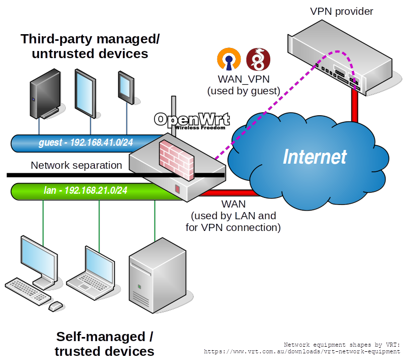
Central in the figure and in the design is the OpenWRT router. It has multiple functions in addition to what routers regularly do:
- Separate two internal network segments.
- Establish a VPN connection.
- Offer a separate internet connection to each internal network.
- Trusted devices (shown in light gray) are those of which the user is in control. It can be reasonably assumed that these do not leak information to the internet for some commercial gain, aside of explicit actions taken by the user. These devices are placed in the ’lan’ segment, and can therefore use the internet connection directly.
- Untrusted devices (shown in dark gray) are devices that the user does not have (full) control of. This can also include any device of which commercial exploitation of the device itself does not end after the user purchases it. These devices are put in the ‘guest’ segment, and can only reach the internet through the VPN connection and not directly.
Prerequisites
- A router running OpenWRT. The tested version is 21.02.1, and the model of router used for this guide is a TP-Link Archer C7 V2. Any OpenWRT device is usable, but configuration adjustments are likely necessary due to different interfaces between models and how they are assigned.
- An internet connection. This can be directly or through a private network.
- For a wired network: some way to create separate network segments. This can be on the router itself if it has multiple network interfaces or an embedded managed switch. Otherwise, a single network interface can be combined with a separate managed switch to separate wired traffic.
- For a wireless network: The router requires at least one wireless radio. Alternatively, configure a wired network and add a separate wireless bridge.
Install required packages
Access the router through SSH. Then run:
opkg update
opkg install ip-tiny
opkg install openvpn luci-app-openvpn # For OpenVPN
opkg install wireguard-tools luci-app-wireguard # For WireGuard
A bit of storage space will be used. Installing all of the above packages requires around 800 KB. To save some space, only install the needed VPN packages.
Although the ip command (from Busybox) integrated in default OpenWRT installations is sufficient for forwarding IPv4 traffic, it will fail to mark network routes as being as static. This is not a dealbreaker, but it is quite ugly since it will be harder to make a distinction between dynamically created routes and static routes. The ip command in the ip-tiny package allows this. It is also a prerequisite for adding IPv6 support, a subject discussed later.
Install either OpenVPN or WireGuard, depending on what your VPN server/provider supports. The LuCI package is optional, but recommended for easy configuration through the LuCI web interface.
Throughout this guide, steps to configure OpenWRT both through the web-interface and through the command line will be given. These commands might have to be adjusted to specific router models and configurations. Note that the commands that persistently store and apply the changed configuration on the command line are omitted for most of the tutorial. To do this on the command line, run after making the relevant configuration changes using uci:
uci commit
/etc/init.d/network restart
The first command stores the changed settings persistently instead of only in memory. The second command is only required when interface changes are made. Note that the second command temporarily disables all interfaces. HTTPS and SSH to manage the router re-establish the connection after the relevant interface is up again, but other protocols (especially those routed) might not.
Create a guest network
If you have not done so already, create a guest network in its own VLAN. If you already have a guest network then you can skip this step. You might still want to read it to confirm that you have a similar configuration as the one that will be used throughout the rest of this guide.
Create a VLAN for a wired network
These instructions assume that the used router has an embedded managed switch. If the router only has direct network interfaces, skip to the end.
By default, VLANs are assigned based on the OpenWRT version and the device type. There are configurations which use VLAN 1 on the WAN interface, while other configurations assign VLAN 1 to the LAN interface. Since using VLAN 1 is a bad practice when separating multiple networks over the same interface, this will be changed first. Of course, this should only be done if the WAN connection has no special VLAN requirements.
In LuCI, go to Network -> Switch. First change the VLAN ID of your WAN network (identifiable by its untagged connection to the WAN port) from 1 or 2 to 11. Also change the VLAN ID of your LAN network from 1 or 2 to 21. Leaving space between VLAN IDs is often a good practice to prepare for any further network segmentation in the future. In the example figure at the beginning of this guide an IP range of 192.168.21.0/24 is used for the LAN network. This might be different for your network, and it is unnecessary to change this.
Now create a new VLAN with VLAN ID 41, which will be the guest network. Configure for this VLAN the embedded Ethernet adapters of the router with the same tagged configuration as VLAN ID 21 (the LAN interface).
In the default configuration all the LAN ports of the switch are assigned as untagged to the LAN network (VLAN 21). From VLAN 21, pick one LAN port and change the configuration from untagged to off. For the same LAN port, change for VLAN ID 41 the configuration from off to untagged.
While you are working here, you might as well use fill OpenWRT’s new VLAN description fields. The result should look something like this:
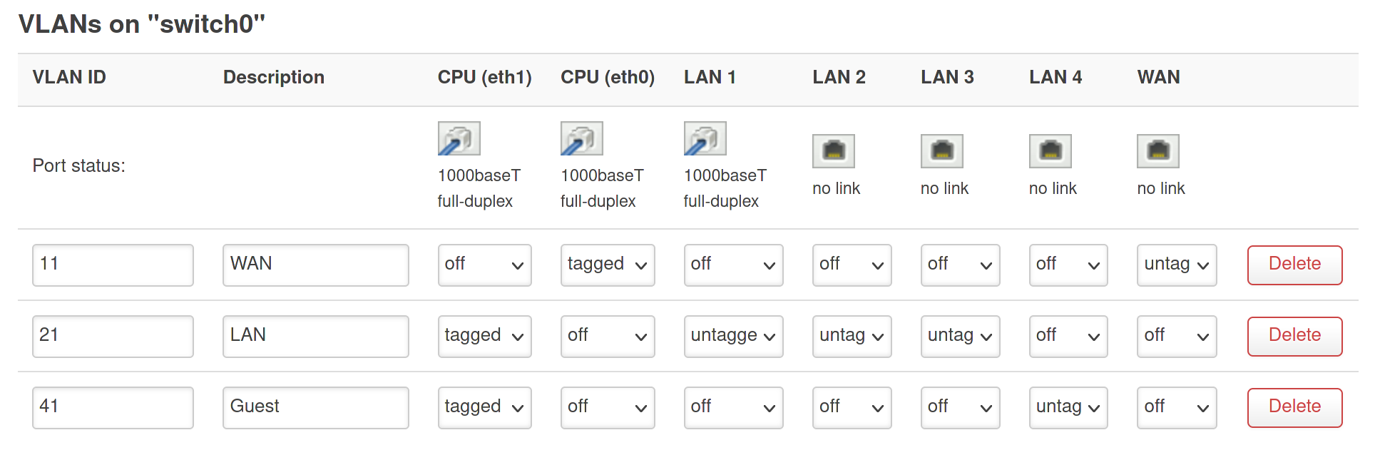
In the figure the Ethernet port with the label LAN 4 is exclusively used to connect guest network devices. Traffic is separated from ’trusted’ LAN on LAN 1 to LAN 3, even though both networks connect to the same internal Ethernet adapter (eth1).
If your router does not have an embedded managed switch and only a single LAN port, connect a separate managed switch to the LAN port. Configure the router’s single LAN interface to have a tagged VLAN 21 and a tagged VLAN 41, similar to the first two columns in the figure above. Configure the managed switch to accept tagged VLAN 21 and 41 on the port that has your router connected, and seperate them untagged over (at least) two different other ports.
It could also be that you have a newer OpenWRT device which offers a distinct network interface for each port. In this case, adapt the configuration to what you need. It is likely that you can dedicate an entire network interface to the guest network, and that you do not have to configure VLANs at all.
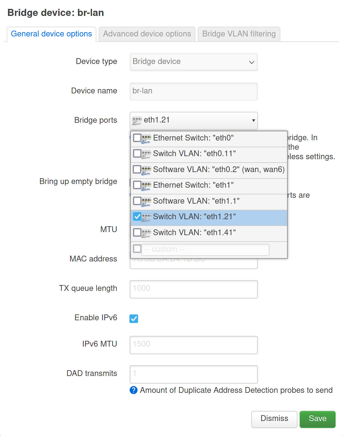
Use Save, but do not apply the new settings yet. If you would apply them now, chances are that you will lock yourself out of accessing your router. The router’s interface (eth1) is used in a bridge interface to manage the same LAN network wired and wirelessly. For the wired network, the bridge uses a specific VLAN on eth1. This was 1 or 2, but now needs to be changed to 21.
In LuCI, go to Network -> Interfaces -> Devices. Configure interface br-lan. Remove bridge port Software VLAN: “ethX.1” and add Switch VLAN: “ethX.21”. Also see the following screenshot:
Use Save to close the dialog. Now do the same for the WAN and WAN6 interfaces, which use either VLAN 1 or 2, but which will be VLAN 11 in the new configuration. In LuCI, go to Network -> Interfaces -> Interfaces. Edit the WAN and WAN6 interfaces. Replace device Software VLAN: “ethX.2” with Switch VLAN: “ethX.11”:
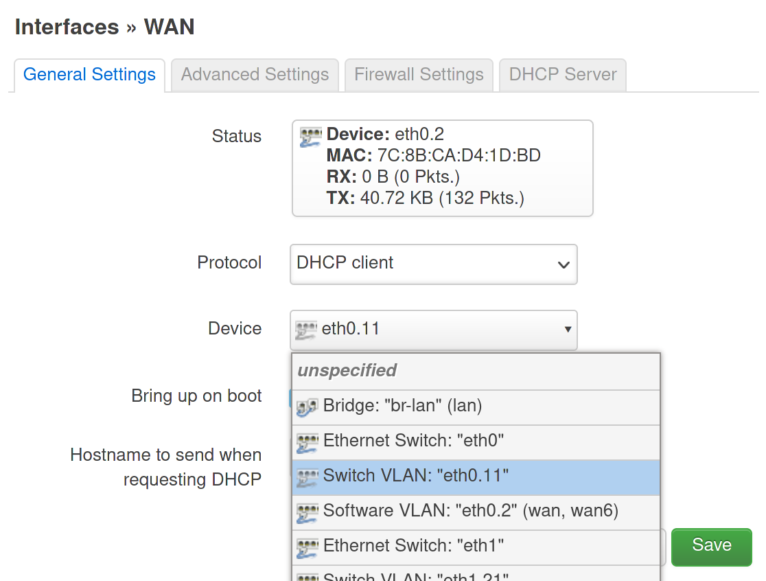
Use Save to close the dialog, and Save & Apply to apply the new configuration.
UCI commands:
uci set network.cfg091ec7.description='WAN'
uci set network.cfg091ec7.vid='11'

uci set network.wan.device='eth0.11'
uci set network.wan6.device='eth0.11'

uci set network.cfg081ec7.description='LAN'
uci set network.cfg081ec7.vid='21'
uci set network.cfg081ec7.ports='0t 2 3 4'

uci del_list network.cfg030f15.ports='eth1.1'
uci add_list network.cfg030f15.ports='eth1.21'

uci add network switch_vlan
uci set network.@switch_vlan[-1].device='switch0'
uci set network.@switch_vlan[-1].description='Guest'
uci set network.@switch_vlan[-1].vlan='41'
uci set network.@switch_vlan[-1].vid='41'
uci set network.@switch_vlan[-1].ports='0t 5'
Create a wireless network
Go to Network -> Wireless. Use the Add button of one of the available radios to add a(n additional) wireless network. On the Interface Configuration -> General Setup tab, use:
- Mode: Access point
- ESSID:
guest(or something more unique) - Network: unspecified
- Hide ESSID: unchecked
- WMM Mode: checked
On the Interface Configuration -> Wireless Security tab, use:
- Encryption: WPA2-PSK or WPA3-SAE, depending on your compatibility needs
- Key: (something unique, long and complex)
Use Save. Once returned to the wireless configuration overview page, use Save & Apply.
UCI commands:
uci set wireless.wifinet2=wifi-iface
uci set wireless.wifinet2.device='radio0'
uci set wireless.wifinet2.mode='ap'
uci set wireless.wifinet2.ssid='guest'
uci set wireless.wifinet2.encryption='psk2'
uci set wireless.wifinet2.key='SecretKey'
These steps can be repeated to cover more wireless frequencies, if multiple wireless radios are available.
Create a guest bridge device
In LuCI, go to Network -> Interfaces -> Devices, and choose Add device configuration. Use the following settings to create the bridge and add the wired guest VLAN:
- Device type: Bridge device
- Device name:
bridge-guest - Bridge ports: Switch VLAN: “ethX.41”
Leave all other settings on their default values. Use Save to close the dialog, and Save and Apply to create the bridge.
uci add network device
uci set network.@device[-1].type='bridge'
uci set network.@device[-1].name='bridge-guest'
uci add_list network.@device[-1].ports='eth1.41'
The wireless network interface will be added to the bridge in the next step, after the guest interface is created.
Create a guest interface
On the router, go to Network -> Interfaces.
Use the button Add new interface. Use the following data:
- Name of the new interface:
guest - Protocol of the new interface: Static address
- Device of the new interface: Bridge: “bridge-guest”
Confirm with Create interface. After the interface is created, its configuration is opened on the General Settings tab. Configure it as follows:
- IPv4 address:
192.168.41.1 - IPv4 netmask:
255.255.255.0
The subnet is chosen based on the VLAN ID, which makes network management a bit easier. Leave all the other fields on this tab default.
On the Advanced Settings tab, configure:
- Delegate IPv6 prefixes: unchecked
Do not worry about IPv6 for now. IPv6 support on the guest interface will be added later.
Do not add a firewall zone yet on the Firewall Settings tab. It is easier to do this later, when the VPN connection is established.
Open the DHCP Server tab and choose Set up DHCP Server. New subtabs will appear. Leave the default values on the General Setup subtab for what they are. Open the Advanced Settings subtab. Add the value 6,9.9.9.9,149.112.112.112 to DHCP-Options. This will point hosts on the guest network to DNS servers on the internet, which they will need since the DNS server of the router will be unavailable in the guest network. Use Save to close the dialog.
To add the previously created wireless guest network to the same interface, go to Network -> Wireless and Edit the corresponding wireless network configuration. For the Network configuration value, replace unspecified with guest. Use Save to close the dialog. Repeat this step for every radio the wireless guest network will be offered on.
Once returned to the wireless configuration page, use Save & Apply to apply the settings.
UCI commands:
uci set network.guest=interface
uci set network.guest.type='bridge'
uci set network.guest.proto='static'
uci set network.guest.device='bridge-guest'
uci set network.guest.ipaddr='192.168.41.1'
uci set network.guest.netmask='255.255.255.0'
uci set network.guest.delegate='0'

uci set dhcp.guest=dhcp
uci set dhcp.guest.interface='guest'
uci set dhcp.guest.start='100'
uci set dhcp.guest.limit='150'
uci set dhcp.guest.leasetime='12h'
uci add_list dhcp.guest.dhcp_option='6,9.9.9.9,149.112.112.112'
uci add_list dhcp.guest.ra_flags='none'

uci set wireless.wifinet2.network='guest'
Configure guest network routing
Routes configure how traffic flows between different networks. In this part of the guide the guest network is prepared to use a different routing configuration from other traffic. This needs to be performed over SSH.
Define a separate routing table for the guest network. The following values are based on the VLAN ID and the interface name, respectively. As with the use of the VLAN ID in the IP address, this makes troubleshooting less of a headache.
cat << 'EOF' >> /etc/iproute2/rt_tables
41      guest
EOF
Now add a script that implements policy-based routing when the guest interface connects or disconnects.
cat << 'EOF' > /etc/hotplug.d/iface/99-guest
#!/usr/bin/env sh

if=guest

dev=$DEVICE
table=$INTERFACE

if2dev() {
  dev=$(uci get network.$1.ifname)
  [ $(echo $dev | wc -w) -gt 1 ] && dev=br-$1
  echo $dev
}

if [ "$INTERFACE" == "$if" ]; then
  if [ "$ACTION" == "ifup" ]; then
    ip rule add iif $dev lookup $table
  elif [ "$ACTION" == "ifdown" ]; then
    # Workaround for missing $DEVICE when interface is going down
    dev=$(if2dev $if)
    ip rule del iif $dev lookup $table
  fi
fi
EOF
When the guest interface is started this script adds a new routing rule which will state that all packets from this interface must use a separate routing table. By default new routing rules are made with a higher priority. Therefore the guest interface will be unable to use the main routing table. When the interface is stopped the script also cleans up the rule.
Files in /etc/hotplug.d are not part of backups or files that survive a firmware upgrade. This is due to that new OpenWRT releases can have newer included hotplug scripts, which replace older rules (and should not be restored from a backup). Add the newly created script to the backup file list as a single file:
cat << 'EOF' >> /etc/sysupgrade.conf
/etc/hotplug.d/iface/99-guest
EOF
Configure a VPN interface
This guide will not go into the specifics of creating a VPN configuration. Just get an OpenWRT or WireGuard configuration file (preferably tailored to use with a Linux client) from a VPN provider if you do not know how to create your own.
Configure OpenVPN
First create a script that adds and removes a default gateway route to the guest routing table, based on the state of the VPN connection:
mkdir -p /etc/openvpn
cat << 'EOF' > /etc/openvpn/routes-guest.sh
#!/usr/bin/env sh

table=guest

if [ "$script_type" == "route-up" ]; then
  ip route add default via $route_vpn_gateway dev $dev table $table proto static
elif [ "$script_type" == "route-pre-down" ]; then
  ip route del default via $route_vpn_gateway dev $dev table $table proto static
fi
EOF
chmod +x /etc/openvpn/routes-guest.sh
Add OpenVPN’s separate configuration directory to OpenWRT’s backups:
cat << 'EOF' >> /etc/sysupgrade.conf
/etc/openvpn/
EOF
In LuCI, go to VPN -> OpenVPN. Use the OVPN configuration file upload function to upload an OpenVPN client configuration. Once the configuration is uploaded, edit it. Append the following:
route-noexec
script-security 2
route-up /etc/openvpn/routes-guest.sh
route-pre-down /etc/openvpn/routes-guest.sh
These commands ensure that OpenVPN will not add routes that the server pushes to the routing table, and that it will run the earlier created script whenever a connection is established or ready to be disconnected.
If you need to use a username and password, add a auth-user-pass line with the file name shown between parentheses above the bottom text box as a single argument, and enter your username and password (one on each line) in the bottom text box. Make sure to finish the second line with the press of the Enter button, so there is a third (empty) line.
Finally, change dev tun to dev tunN, where N is the number of the TUN network interface the VPN will use. If this is the only or first VPN to be configured, dev tun0 will suffice. Otherwise, check the command ip addr and see which tun interfaces already exist. The correct integer to use for N is one higher than the current highest value. Also make sure that the other VPN configurations also have their own dev tunN line to explicitly assign them to a network interface. This avoids mixed interface assignments with multiple OpenVPN configurations.
Use Save once you are done editing the OpenVPN configuration. On the VPN -> OpenVPN page, enable the new configuration and use Save & Apply. Check to see if the VPN starts correctly in Status -> System Log.
Go to Network -> Interfaces and use the option Add new interface…. Use the following settings.
- Name:
wan_vpn - Protocol: Unmanaged
- Interface: Ethernet Adapter: “tunN” (where N is the previously explicitly assigned TUN network interface number).
Use Create interface. In the interface settings go to the Advanced Settings tab and disable Delegate IPv6 prefixes. Then use Save to close the interface settings. Use Save & Apply to commit all new settings.
UCI commands:
uci set openvpn.wan_vpn=openvpn
uci set openvpn.wan_vpn.config='/etc/openvpn/wan_vpn.ovpn'

uci set network.wan_vpn=interface
uci set network.wan_vpn.ifname='tun0'
uci set network.wan_vpn.proto='none'
uci set network.wan_vpn.delegate='0'
The TUN interface is ‘Unmanaged’ by OpenWRT since OpenVPN manages the IP configuration. The only reason this interface is created is so that a firewall zone can be assigned later.
Configure WireGuard
This section assumes that a WireGuard configuration file is available. This file cannot directly be imported into OpenWRT. For configuration through LuCI and UCI, references will be made to the configuration’s [Section]-Values.
WireGuard does not allow servers to push routes, unlike OpenVPN. This is why this guide assumes that the VPN is configured at the server to let the client route all traffic through the VPN. This server-side configuration can be verified by examining the provided WireGuard client configuration file. If the values for [Peer]-AllowedIPs are 0.0.0.0/0 and ::/0 (sometimes written as ::0/0), and the address prefix in [Interface]-Address is /32 for IPv4 and /128 for IPv6, then this guide can be followed without any routing adjustments.
In LuCI, go to Network -> Interfaces. Choose Add new interface.
Hint: If WireGuard VPN is unavailable to choose as a protocol after installing the relevant packages, run /etc/init.d/network restart and refresh the web page. Alternatively, reboot the router.
Configure as follows:
- Name:
wan_vpn - Protocol: WireGuard VPN
Use Create interface. Configure the General Settings tab as follows:
- Protocol: WireGuard VPN
- Bring up on boot: checked
- Private Key: ([Interface]-PrivateKey)
- Listen Port:
10041 - IP addresses: ([Interface]-Address, add each address individually instead of everything on one line)
- No Host Routes: checked
Port 10041 is meant to support incoming connections. Since the WireGuard listening port is not disabled and random by default, a best practice is to put it on an unused fixed port. The 41 at the end is a reference to the VLAN ID and routing table number of the guest interface. 10000 is added since it prevents services that use lower port numbers from conflicting.
Disable ‘Delegate IPv6 prefixes’ on the Advanced Settings tab. On the peers tab, use Add peer and add the following:
- Description:
WireGuard VPN client connection to (name of VPN provider) - Public Key: ([Peer]-PublicKey)
- Preshared Key: ([Peer]-PresharedKey), leave empty if missing in configuration file
- Allowed IPs: ([Peer]-AllowedIPs), add each address range individually instead of everything on one line
- Route Allowed IPs: Unchecked
- Endpoint Host: ([Peer]-Endpoint), but only the host before the colon
- Endpoint Port: ([Peer]-Endpoint), but only the port number after the colon
- Persistent Keep Alive: ([Peer]-PersistentKeepalive), leave empty or 0 if missing in configuration file, or set to 25 if WAN interface of the router is connected through a NAT to the internet and not directly
Use Save. Back on the Network -> Interfaces page, use Save & Apply.
UCI commands:
uci set network.wan_vpn=interface
uci set network.wan_vpn.proto='wireguard'
uci add network wireguard_wan_vpn
uci set network.wan_vpn.listen_port='10041'
uci set network.wan_vpn.private_key='([Interface]-PrivateKey)'
uci add_list network.wan_vpn.addresses='([Interface]-Address, add each address individually instead of everything on one line)'
uci set network.wan_vpn.nohostroute='1'
uci set network.wan_vpn.delegate='0'

uci set network.@wireguard_wan_vpn[-1].description='WireGuard VPN client connection to (name of VPN provider)'
uci set network.@wireguard_wan_vpn[-1].endpoint_host='([Peer]-Endpoint, but only the host before the colon)'
uci set network.@wireguard_wan_vpn[-1].endpoint_port='([Peer]-Endpoint, but only the port number after the colon)'
uci set network.@wireguard_wan_vpn[-1].public_key='([Peer]-PublicKey)'
uci set network.@wireguard_wan_vpn[-1].persistent_keepalive='0'
uci add_list network.@wireguard_wan_vpn[-1].allowed_ips='([Peer]-AllowedIPs, add each address range individually instead of everything on one line)'
Use SSH to create a script that adds a default gateway route to the guest routing table whenever a connection is established by the WireGuard VPN interface:
cat << 'EOF' > /etc/hotplug.d/iface/99-wan_vpn
#!/usr/bin/env sh

if=wan_vpn
table=guest

dev=$DEVICE

if [ "$INTERFACE" == "$if" ]; then
  if [ "$ACTION" == "ifup" ]; then
    ip route add default dev $dev table $table proto static
  fi
fi
EOF
The route is automatically removed when the WireGuard VPN interface stops, so the script does not need to handle this.
Add the script to the backup file list as well:
cat << 'EOF' >> /etc/sysupgrade.conf
/etc/hotplug.d/iface/99-wan_vpn
EOF
Configure the firewall
The VLAN configuration and/or separate wireless network configuration ensures that the guest network is separated on the data link OSI layer. Since there is no firewall configured, no traffic routing between networks is allowed on the network and higher layers to the router and beyond. TUN and WireGuard VPN interfaces only operate on the network OSI layer and higher. Therefore, firewall configuration is needed to allow traffic between the guest interface and the VPN interface. The first step is to add firewall zones for the guest network and for the VPN interface.
In LuCI, go to Network -> Firewall -> General Settings. Add a new zone. Use the following settings on the General Settings tab.
- Name:
wan_vpn - Input: reject
- Output: accept
- Input: reject
- Masquerading: checked
- MSS clamping: checked
- Covered networks: wan_vpn
Use Save to save the firewall zone. Choose Add again to add another firewall zone.
- Name:
guest - Input: reject
- Output: accept
- Forward: reject
- Masquerading: unchecked
- MSS clamping: unchecked
- Covered networks: guest
- Allow forward to destination zones: wan_vpn
Use Save to save the firewall zone. Back on the firewall settings page, use Save & Apply to create the new zones.
UCI commands:
uci add firewall zone
uci set firewall.@zone[-1].name='wan_vpn'
uci set firewall.@zone[-1].input='REJECT'
uci set firewall.@zone[-1].output='ACCEPT'
uci set firewall.@zone[-1].forward='REJECT'
uci set firewall.@zone[-1].masq='1'
uci set firewall.@zone[-1].mtu_fix='1'
uci add_list firewall.@zone[-1].network='wan_vpn'

uci add firewall zone
uci set firewall.@zone[-1].name='guest'
uci set firewall.@zone[-1].input='REJECT'
uci set firewall.@zone[-1].output='ACCEPT'
uci set firewall.@zone[-1].forward='REJECT'
uci add_list firewall.@zone[-1].network='guest'

uci add firewall forwarding
uci set firewall.@forwarding[-1].src='guest'
uci set firewall.@forwarding[-1].dest='wan_vpn'
Forwarded traffic is allowed but due to that ‘Input’ is rejected, all direct traffic from the guest network destined for the router itself is denied. The guest network needs DHCP for automatic IPv4 address configuration, which is why it needs to be enabled in the firewall as an exception. In LuCI, go to Network -> Firewall -> Traffic rules. Add a new rule:
- General Settings
- Name:
Allow-Guest-Input-DHCPv4 - Protocol: UDP
- Source zone: guest
- Source port:
68 - Destination zone: Device (input)
- Destination port:
67 - Action: accept
- Name:
- Advanced Settings
- Restrict to address family: IPv4 only
Use Save and Save & Apply.
UCI commands:
uci add firewall rule
uci set firewall.@rule[-1].name='Allow-Guest-Input-DHCPv4'
uci set firewall.@rule[-1].family='ipv4'
uci add_list firewall.@rule[-1].proto='udp'
uci set firewall.@rule[-1].src='guest'
uci set firewall.@rule[-1].src_port='68'
uci set firewall.@rule[-1].target='ACCEPT'
uci set firewall.@rule[-1].dest_port='67'
Restart interfaces
Several configuration changes and scripts were added in the previous steps. To ensure that they are all applied, the interfaces and VPN connection must be restarted. Restart the ‘guest’ and ‘wan_vpn’ interfaces on the Network -> Interface page in LuCI.
If OpenVPN is used, restart the OpenVPN instance on the VPN -> OpenVPN page. This separate step is not necessary for WireGuard since its state is equal to the state of the relevant network interface.
The same can be done on the command line:
uci commit # To 'Save' all changes to persistent storage
/etc/init.d/network restart # To 'Apply' all changes
/etc/init.d/openvpn restart # Only when OpenVPN is used
Test the connection
Some useful tests, which also help to diagnose common problems.
- First of all, test if your internet connection works normally on the LAN network. If there are problems, it is almost certain the next steps will not work either.
- Connect a computer configured to request IP information through DHCP to the guest network. See if the received IP configuration makes sense (Linux:
ip addr;route -n;cat /etc/resolv.conf;resolvectl status, Windows:ipconfig /all). The IP address of the relevant interface should be in the 192.168.41.0/24 range, the default gateway should be 192.168.41.1, and the configured DNS servers should be 9.9.9.9 and 149.112.112.112. If these addresses are not as expected, verify the DHCP configuration for the guest network. If no address is assigned at all, check both the DHCP configuration and the wired (VLAN) or wireless network configuration, depending on what you are using. - Check if there is an internet connection. Try
ping 9.9.9.9. Receiving a reply implies that some form of internet connection is available, since the DNS server of Quad9 can be reached. Read ahead after this list of tests if you encounter problems at this point. - Verify if DNS works. Try
nslookup dns.quad9.net. In the answer should be the addresses 9.9.9.9 and 149.112.112.112. - Run a traceroute (Linux:
traceroute dns.quad9.net, Windows:tracert dns.quad9.net). It shows which gateway is used to access the internet as the first hop. For the guest network this should be 192.168.41.1. The next hops show which path to the VPN provider and on the internet is followed. This should differ significantly from a traceroute to the same address from the LAN network. - Check which source IP address is used to connect to remote hosts on the internet from the guest network. One example of where you can do this is WhatIsMyIp.com. This address should be different from the WAN IP address, which can checked by visiting the same site using the LAN network.
- Check if network segmentation works. Try pinging 192.168.41.1, 192.168.21.1 (or whatever the default gateway is on the LAN network), and an active host on your LAN network if there is any. You should not receive any replies.
If you have any trouble with test 3, verify that a VPN connection is successfully established. For OpenVPN, see in LuCI Status -> System Log. For WireGuard, check Status -> WireGuard. If it fails, check to see why it does. First ensure that you can successfully set up a VPN connection using a PC. Also, ensure that you do not have two VPN connections with the same credentials at the same time. Most VPN server-side software and VPN providers will not accept this.
If a VPN connection is successfully established, verify the routing configuration. You can check this with:
ip rule show table guest
ip route show table guest
If the first command give empty results, check whether /etc/hotplug.d/iface/99-guest is configured correctly. If the last command gives an empty result, check /etc/openvpn/routes-guest.sh (for OpenVPN) or /etc/hotplug.d/iface/99-wan_vpn (for WireGuard).
A ’table id value is invalid’ error from any command implies an incorrectly configured /etc/iproute2/rt_tables.
Add IPv6 support
To enable IPv6 a few actions have to be performed:
- Install necessary packages
- Add an IPv6 address and prefix to the guest network interface
- Enable automated address assignment on the guest network
- Add NAT6 support
- Update scripts to support IPv6
Install additional packages
Additional packages are needed to configure IPv6 routing and to support NAT6 with IPv6 masquerading. To install these, run in SSH on the router:
opkg update
opkg install ip-tiny kmod-ipt-nat6 ipset
Add an IPv6 address and prefix to the guest interface
The following commands will generate and add a unique local address to the guest interface. It does so by:
- Defining the first byte as 0xfd (8 bits). The first 7 bits of this ‘Prefix’ represent the address space for unique local addresses, and the eighth bit represents local assignment of the address.
- Generating the next 5 bytes (40 bits) randomly. The ‘Prefix’ and this ‘Global ID’ concern an IPv6 48 bit routing prefix.
- Assigning ‘Subnet ID’ 0 (the next 16 bits) statically. When this is combined with the routing prefix it creates a 64 bit network prefix.
- Assigning ‘Interface ID’ 1 (the next 64 bits) statically. These 64 bit are the interface identifier.
For background information, see Wikipedia, RFC 4193, RFC 4291 and RFC 5375.
Run:
lagId=$(hexdump -vn 5 -e ' /1 "%02x"' /dev/urandom)
ipv6Address=fd${lagId:0:2}:${lagId:2:4}:${lagId:6:4}::1/64
uci add_list network.guest.ip6addr=$ipv6Address
uci commit network
/etc/init.d/network restart
You can see the configured address in LuCI (Network -> Interfaces -> Guest), UCI (uci get network.guest.ip6addr), and with ip addr.
Enable automated IPv6 assignment on the guest network
There are two methods of automated IPv6 assignments. There is stateless address autoconfiguration (SLAAC), also referred to as ‘Router Advertisement’. It tells new nodes the network prefix they can use. Each node generates its own interface identifier within the range of the network prefix. SLAAC uses the Neighbor Discovery Protocol to communicate routing and DNS addresses (see RFC 8106].
DHCPv6 is the stateful alternative, which makes the router keep track of each assigned address. DHCPv6 is useful if firewall rules have to be made for individual nodes in a network or if additional DHCPv6 options have to be exchanged (DNS hostnames, WINS addresses, etc.). Not all operating systems support DHCPv6. For example, Android and ChromeOS lack DHCPv6 support. Look here for a list of which operating systems support DHCPv6.
For the guest network, the router does not need to keep track of addresses of individual nodes. Furthermore, there is no need to exchange additional DHCPv6 options. For compatibility and simplicity, only SLAAC will be configured.
In LuCI, go to Network -> Interfaces. Edit the guest interface. Go to DHCP Server -> IPv6 Settings. Configure as follows:
- Designated master: unchecked
- RA-Service: server mode
- DHCPv6-Service: disabled
- NDP-Proxy: disabled
Now switch to the IPv6 RA Settings subtab. Configure as follows:
- Default router: on available prefix
- Enable SLAAC: checked
Leave the other options on their default values. Use Save and Save & Apply.
Unfortunately, due to a bug it is not possible to configure SLAAC-only DNS configuration announcement within LuCI. This can be configured using SSH. See the last two UCI commands, which configure SLAAC to announce Quad9’s public IPv6 DNS servers. Do not forget to run uci commit dhcp afterwards to store and apply the settings.
UCI commands:
uci set dhcp.guest.ra='server'
uci set dhcp.guest.ra_default='1'
uci add_list dhcp.guest.dns='2620:fe::fe'
uci add_list dhcp.guest.dns='2620:fe::9'
A firewall exception is required to allow the router to receive Neighbor Discovery Protocol packets from nodes on the guest interface. Go to Network -> Firewall -> Traffic Rules. Add a new rule:
- General Settings
- Name:
Allow-Guest-Input-NDP - Protocol: ICMP
- Source zone: guest
- Destination zone: Device (input)
- Action: accept
- Name:
- Advanced Settings
- Restrict to address family: IPv6 only
- Match ICMP type: neighbour-advertisement, neighbour-solicitation and router-solicitation
Use Save and Save & Apply.
UCI commands:
uci add firewall rule
uci set firewall.@rule[-1].name='Allow-Guest-Input-NDP'
uci set firewall.@rule[-1].src='guest'
uci set firewall.@rule[-1].target='ACCEPT'
uci set firewall.@rule[-1].family='ipv6'
uci add_list firewall.@rule[-1].proto='icmp'
uci add_list firewall.@rule[-1].icmp_type='neighbour-advertisement'
uci add_list firewall.@rule[-1].icmp_type='neighbour-solicitation'
uci add_list firewall.@rule[-1].icmp_type='router-solicitation'
Add NAT6 and IPv6 masquerading support
Unlike IPv4, NAT6 and IPv6 masquerading is not recommended. The idea behind IPv6 is that there are so many addressess that masquerading of multiple addresses through a single address is not necessary. However, when one relies on a VPN provider that offers a single IPv6 address (using a /128 prefix), there are no alternatives if multiple devices need to be able to use the VPN connection.
Start by adding a script which will take care of NAT6 and IPv6 masquerading for interfaces which have the relevant option enabled (script based on these sources):
cat << 'EOF' > /etc/firewall.nat6
#!/bin/sh
#
# Masquerading nat6 firewall script.
#
# Place as: /etc/firewall.nat6
# Hook it into the firewall configuration:
#   uci set firewall.nat6="include"
#   uci set firewall.nat6.path="/etc/firewall.nat6"
#   uci set firewall.nat6.reload="1"
#   uci commit firewall
#
# Then you can configure in /etc/config/firewall per zone, ala where you have:
#   option masq 1
# Just drop this in beneath it:
#   option masq6 1
# For IPv6 privacy (temporary addresses used for outgoing), also add:
#   option masq6_privacy 1
#
# Hope it's useful!
#
# https://github.com/akatrevorjay/openwrt-masq6
# ~ trevorj <github@trevor.joynson.io>
#

set -eo pipefail

. /lib/functions.sh
. /lib/functions/network.sh
. /usr/share/libubox/jshn.sh

log() {
    logger -t nat6 -s "$@"
}

get_ula_prefix() {
    uci get network.globals.ula_prefix
}

validate_ula_prefix() {
    local ula_prefix="$1"
    if [ $(echo "$ula_prefix" | grep -c -E "^([0-9a-fA-F]{4}):([0-9a-fA-F]{0,4}):") -ne 1 ] ; then
        log "Fatal error: IPv6 ULA ula_prefix=\"$ula_prefix\" seems invalid. Please verify that a ula_prefix is set and valid."
        return 1
    fi
}

ip6t() {
    ip6tables "$@"
}

ip6t_add() {
    if ! ip6t -C "$@" &>/dev/null; then
        ip6t -I "$@"
    fi
}

nat6_init() {
    iptables-save -t nat \
    | sed -e "/\s[DS]NAT\s/d;/\sMASQUERADE$/d" \
    | ip6tables-restore -T nat
}

masq6_network() {
    # $config contains the ID of the current section
    local network_name="$1"

    local device
    network_get_device device "$network_name" || return 0

    local done_net_dev
    for done_net_dev in $DONE_NETWORK_DEVICES; do
        if [ "$done_net_dev" = "$device" ]; then
            log "Already configured device=\"$device\", so leaving as is."
            return 0
        fi
    done

    log "Found device=\"$device\" for network_name=\"$network_name\"."

    if [ $zone_masq6_privacy -eq 1 ]; then
        log "Enabling IPv6 temporary addresses for device=\"$device\"."

        log "Accepting router advertisements on $device even if forwarding is enabled (required for temporary addresses)"
        echo 2 > "/proc/sys/net/ipv6/conf/$device/accept_ra" \
          || log "Error: Failed to change router advertisements accept policy on $device (required for temporary addresses)"

        log "Using temporary addresses for outgoing connections on interface $device"
        echo 2 > "/proc/sys/net/ipv6/conf/$device/use_tempaddr" \
          || log "Error: Failed to enable temporary addresses for outgoing connections on interface $device"
    fi

    append DONE_NETWORK_DEVICES "$device"
}

handle_zone() {
    # $config contains the ID of the current section
    local config="$1"

    local zone_name
    config_get zone_name "$config" name

    # Enable masquerading via NAT6
    local zone_masq6
    config_get_bool zone_masq6 "$config" masq6 0

    log "Firewall config=\"$config\" zone=\"$zone_name\" zone_masq6=\"$zone_masq6\"."

    if [ $zone_masq6 -eq 0 ]; then
        return 0
    fi

    # IPv6 privacy extensions: Use temporary addrs for outgoing connections?
    local zone_masq6_privacy
    config_get_bool zone_masq6_privacy "$config" masq6_privacy 1

    log "Found firewall zone_name=\"$zone_name\" with zone_masq6=\"$zone_masq6\" zone_masq6_privacy=\"$zone_masq6_privacy\"."

    log "Setting up masquerading nat6 for zone_name=\"$zone_name\" with zone_masq6_privacy=\"$zone_masq6_privacy\""

    local ula_prefix=$(get_ula_prefix)
    validate_ula_prefix "$ula_prefix" || return 1

    local postrouting_chain="zone_${zone_name}_postrouting"
    log "Ensuring ip6tables chain=\"$postrouting_chain\" contains our MASQUERADE."
    ip6t_add "$postrouting_chain" -t nat \
        -m comment --comment "!fw3" -j MASQUERADE

    local input_chain="zone_${zone_name}_input"
    log "Ensuring ip6tables chain=\"$input_chain\" contains our permissive DNAT rule."
    ip6t_add "$input_chain" -t filter -m conntrack --ctstate DNAT \
        -m comment --comment "!fw3: Accept port forwards" -j ACCEPT

    local forward_chain="zone_${zone_name}_forward"
    log "Ensuring ip6tables chain=\"$forward_chain\" contains our permissive DNAT rule."
    ip6t_add "$forward_chain" -t filter -m conntrack --ctstate DNAT \
        -m comment --comment "!fw3: Accept port forwards" -j ACCEPT

    local DONE_NETWORK_DEVICES=""
    config_list_foreach "$config" network masq6_network

    log "Done setting up nat6 for zone=\"$zone_name\" on devices: $DONE_NETWORK_DEVICES"
}

main() {
    nat6_init
    config_load firewall
    config_foreach handle_zone zone
}

main "$@"
EOF
Make the script part of OpenWRT backups:
cat << 'EOF' >> /etc/sysupgrade.conf
/etc/firewall.nat6
EOF
Hook the script into the firewall configuration:
uci set firewall.nat6="include"
uci set firewall.nat6.path="/etc/firewall.nat6"
uci set firewall.nat6.reload="1"
Enable IPv6 masquerading on the VPN interface:
uci set $(uci show firewall | sed -n -e "/\.name='wan_vpn'$/s//.masq6=1/p" | sed -n -e "1p")
uci set $(uci show firewall | sed -n -e "/\.name='wan_vpn'$/s//.masq6_privacy=1/p" | sed -n -e "1p")
See /etc/config/firewall, where the masq6 and masq6_privacy options are added to the zone named ‘wan_vpn’.
Update scripts to also support IPv6
To add IPv6 support some scripts need to be updated.
Update /etc/hotplug.d/iface/99-guest by running:
cat << 'EOF' > /etc/hotplug.d/iface/99-guest
#!/usr/bin/env sh

if=guest

dev=$DEVICE
table=$INTERFACE

if2dev() {
  dev=$(uci get network.$1.ifname)
  [ $(echo $dev | wc -w) -gt 1 ] && dev=br-$1
  echo $dev
}

if [ "$INTERFACE" == "$if" ]; then
  if [ "$ACTION" == "ifup" ]; then
    ip rule add iif $dev lookup $table
    ip -6 rule add iif $dev lookup $table
  elif [ "$ACTION" == "ifdown" ]; then
    # Workaround for missing $DEVICE when interface is going down
    dev=$(if2dev $if)
    ip rule del iif $dev lookup $table
    ip -6 rule del iif $dev lookup $table
  fi
fi
EOF
Update /etc/openvpn/routes-guest.sh by running (for OpenVPN only):
cat << 'EOF' > /etc/openvpn/routes-guest.sh
#!/usr/bin/env sh

table=guest

if [ "$script_type" == "route-up" ]; then
  ip route add default via $route_vpn_gateway dev $dev table $table proto static
  ip -6 route add default via $route_ipv6_gateway_1 dev $dev table $table proto static
elif [ "$script_type" == "route-pre-down" ]; then
  ip route del default via $route_vpn_gateway dev $dev table $table proto static
  ip -6 route del default via $route_ipv6_gateway_1 dev $dev table $table proto static
fi
EOF
Update /etc/hotplug.d/iface/99-wan_vpn by running (for WireGuard only):
cat << 'EOF' > /etc/hotplug.d/iface/99-wan_vpn
#!/usr/bin/env sh

dev=$DEVICE
table=guest

if [ "$INTERFACE" == "wan_vpn" ]; then
  if [ "$ACTION" == "ifup" ]; then
    ip route add default dev $dev table $table proto static
    ip -6 route add default dev $dev table $table proto static
  fi
fi
EOF
Reboot the router or restart the guest and wan_vpn interfaces, and restart the VPN connection. IPv6 should now be supported in the guest network. To test this, simply follow the earlier described test steps, adjusted for IPv6:
- First of all, test if your internet connection works normally on the LAN network. If there are problems, it is almost certain the next will not work either.
- Connect a computer configured to request IP information through SLAAC to the guest network. See if the received IP configuration makes sense (Linux:
ip -6 addr;route -6 -n;cat /etc/resolv.conf;resolvectl status, Windows:ipconfig /all). The IP address of the relevant interface should be in the /64 network prefix that was generated for the guest network interface of the router, the default gateway should be the first IP address in this network, and the configured DNS servers should be 2620:fe::fe and 2620:fe::9. If these addresses are not as expected, verify the IPv6 and SLAAC configuration of the guest network. If no address is assigned at all, check both the IPv6 configuration of the client and the wired (VLAN) or wireless network configuration, depending on what you are using. - Check if there is an internet connection. Try
ping 2620:fe::fe. Receiving a reply implies that some form of internet connection is available, since the DNS server of Quad9 can be reached. Read ahead after this list of tests if you encounter problems at this point. - Verify if DNS works. Try
nslookup dns.quad9.net 2620:fe::fe. The answer should contain the addresses 2620:fe::fe and 2620:fe::9. - Run a traceroute (Linux:
traceroute -6 dns.quad9.net, Windows:tracert -6 dns.quad9.net). It shows which gateway is used to access the internet as the first hop. This should be the IPv6 address of the guest interface of the router. The next hops show which path to the VPN provider and on the internet is followed. This should differ significantly from a traceroute to the same address from the LAN network. - Check which source IP address is used to connect to remote hosts on the internet from the guest network. One example of where you can do this is IPv6 test. This address should be different from the WAN IP address, which can checked by visiting the same site using the LAN network.
- Check if network segmentation works. Try pinging the different IPv6 addresses of the router, and an active host on your LAN network if there is any. You should not receive any replies.